Materials
| Component | Qty | Cost |
|---|---|---|
| Arduino Mega 2560 Rev3 | 2 | $96.80 |
| Arduino Motor Shield Rev3 | 1 | $27.60 |
| 10kΩ Potentiometers | 2 | $3.98 |
| LCD Display | 1 | $9.49 |
| Pushbutton | 1 | $2.50 |
| NRF24L01 2.4GHz Transceiver | 2 | $12.19 |
| Micro Servo Motor | 1 | $3.50 |
| Maxon Motor & Gearbox | 2 | $18.99 |
| Piezo Buzzer | 1 | $1.50 |
| Total | $176.55 |
How It Works
Transmitter (Controller)
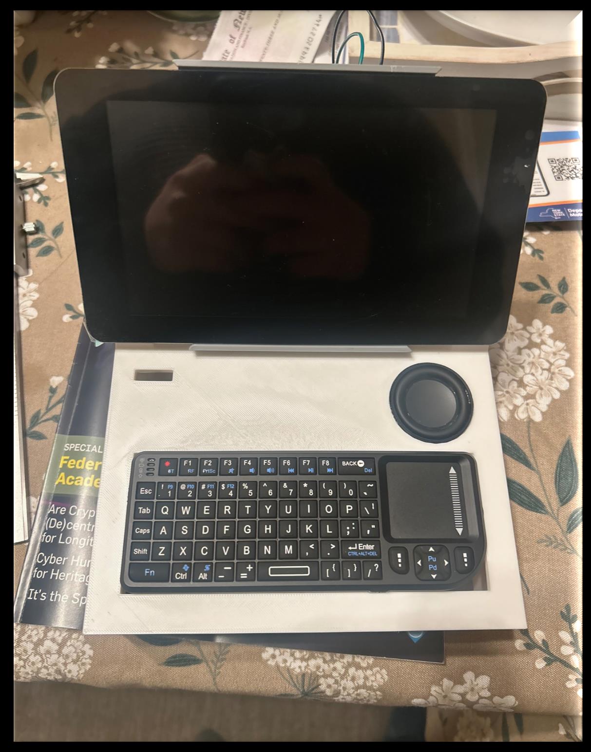
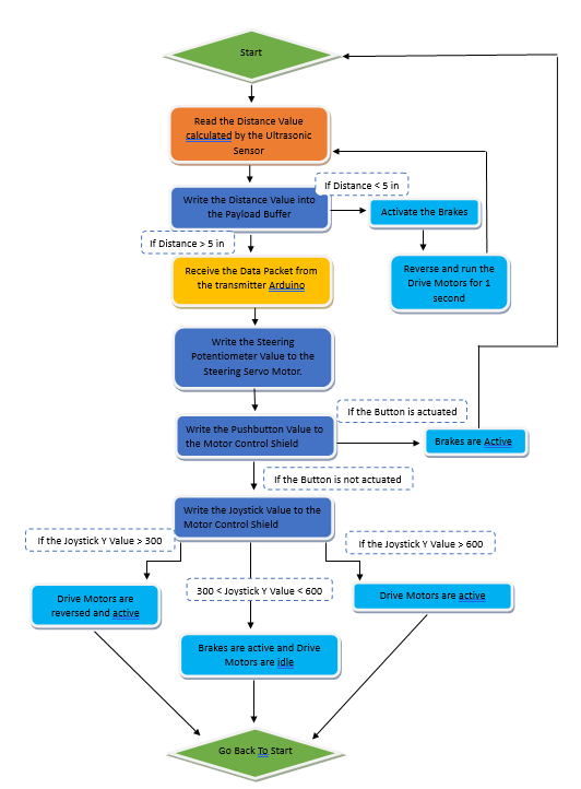
Two potentiometers control steering and throttle. A pushbutton triggers an obstacle-detection sweep. An LCD displays the live distance reading from the car's ultrasonic sensor. The NRF24L01 module sends control packets to the car at regular intervals.
Receiver (Car)
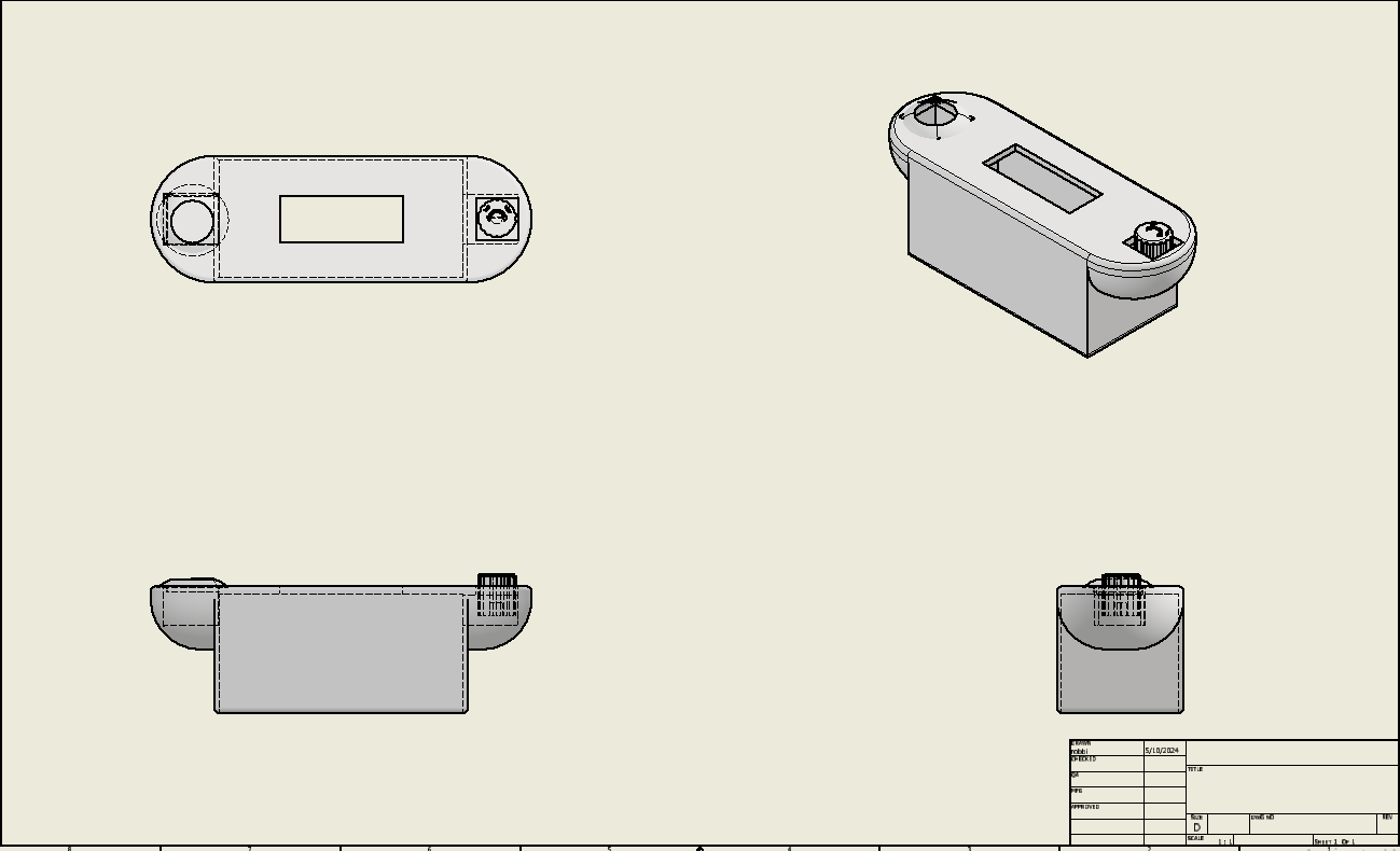
An HC-SR04 ultrasonic sensor sits on a micro servo, allowing it to sweep and scan for obstacles. The Motor Shield drives two Maxon DC gearbox motors for drive, and a separate servo handles steering via the 3D-printed rack and pinion. A piezo buzzer increases in frequency as obstacles get closer. All incoming control data is processed by the second Arduino Mega.
Transmitter: handheld controller with LCD and potentiometers
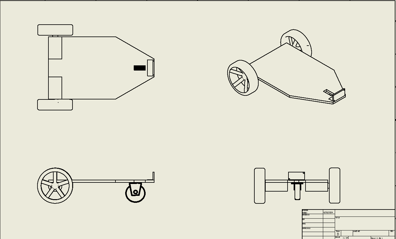
Receiver: car chassis with Motor Shield and ultrasonic sensor
Transmitter circuit: Arduino Mega, NRF24L01, potentiometers
Receiver circuit: Motor Shield, NRF24L01, HC-SR04
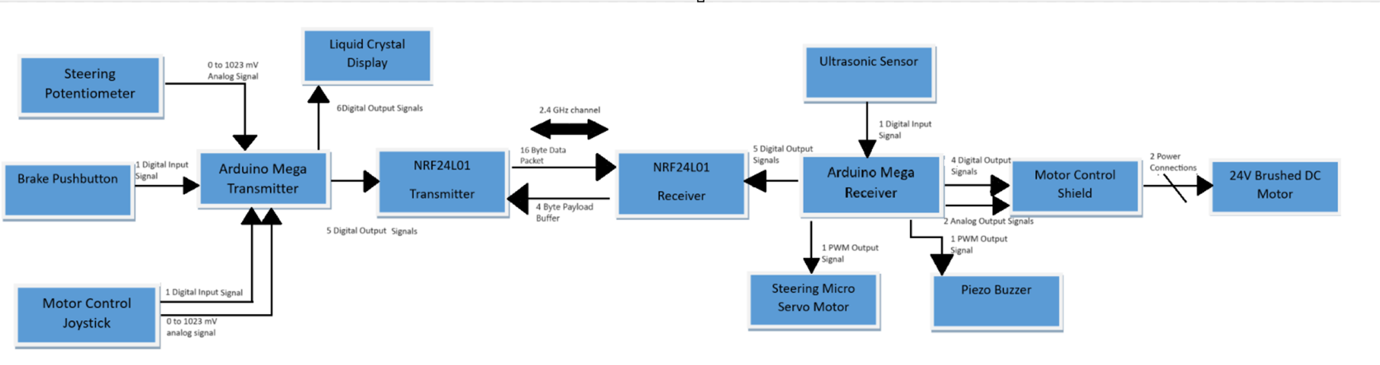
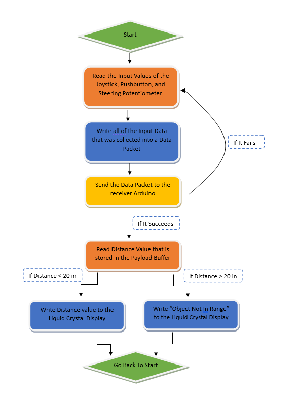
System block diagram
Challenges
RF transceiver reliability tanks when you're under-powering the module. Spent hours debugging what turned out to be a voltage issue: the NRF24L01 needs a stable 3.3V supply, not pulled from the Arduino's regulator under load.
- 3D printing the rack-and-pinion steering: several failed prints due to bed adhesion issues. Solved with Elmer's glue on the print bed.
- Power distribution: two Arduinos, a motor shield, and RF modules all competing for clean voltage required careful decoupling
- Chassis design didn't account for wire routing; the second version had proper channels built in
Future Work
- Faster motors and refined 3D-printed suspension geometry
- Speedometer via onboard accelerometer
- Expanded LCD menu showing battery voltage and signal strength
- Onboard FPV camera for remote viewing