Capstone project for ETC 423: Microprocessor Interfacing at SUNY Polytechnic Institute, completed December 2025. Built with Rejhan Karajkovic, Admir Munjakovic, and Ater Lay.
The idea came from watching predictive maintenance teams in industrial environments. They carry thermal readers, ultrasonic probes, and various specialized devices, all separately and each requiring their own setup. The portable sensor bay combines those capabilities into a single platform built around a Raspberry Pi 5 and a 7-inch touchscreen. Sensors connect via I2C and are hot-swappable: no rewiring, no reconfiguration between swaps.
Target user: a technician on the floor of an Amazon fulfillment center who needs to check machinery health on the move, with minimal downtime between checks.
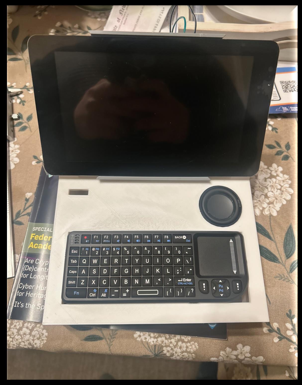
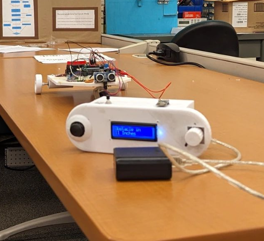
Assembled device: 7" touchscreen, 3D-printed enclosure, mini keyboard
TOPSOIL
Hardware
Component
Qty
Cost
Raspberry Pi 5 (16 GB RAM)
1
$132.00
Pi Foundation 7" Touchscreen Display
1
$79.95
AMG8833 8×8 IR Thermal Camera
1
$35.59
Mini Keyboard with Touchpad
1
$22.99
Official Raspberry Pi 27W USB-C Power Supply
1
$14.04
Raspberry Pi 5 Active Cooler
1
$13.50
Adafruit MAX98357A I2S 3W Class D Amplifier
1
$5.95
Speaker, 40mm 4Ω 5W
1
$4.95
Total
$308.97
System Design
Sensor Interface
All sensors communicate over I2C, routed through a dedicated port on the enclosure. Hot-swapping works because I2C supports multiple devices on the same bus; each sensor is addressed individually, so removing one and attaching another requires no changes to the wiring harness or power routing. DuPont connectors handle the connections for now; the plan is to swap them for watertight Deutsch connectors in a future revision.
Audio Feedback
A MAX98357A I2S Class D amplifier drives a 40mm speaker for audible alerts and status cues. I2S was chosen over PWM audio for cleaner output and lower CPU overhead on the Pi.
MAX98357A I2S Amplifier Wiring
Pin
Connects To
VIN
5V
GND
Ground
DIN
I2S Data
BCLK
I2S Bit Clock
LRC
I2S Left/Right Clock
SPK+
Speaker +
SPK−
Speaker −
I2C Sensor Wiring
Pin
Connects To
VDD
3.3V or 5V
SDA
SDA pin
GND
Ground
SCL
SCL pin
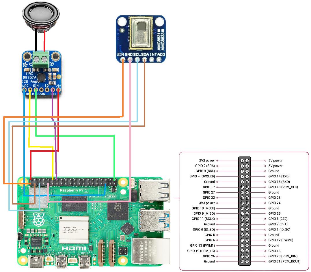
Full wiring schematic for Raspberry Pi 5, AMG8833 thermal camera, and MAX98357A I2S amplifier
Thermal Camera Software
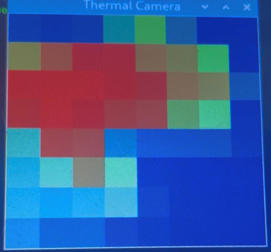
The AMG8833 produces an 8×8 grid of temperature readings. The Python script reads the array, maps each value to an ironbow-style RGB color, builds a PIL image, and upscales it to 300×300px for display in a tkinter window. The loop runs every 50ms (~20 FPS).
Temperature bounds are recalculated each frame so the colormap autoscales to the current range
Ironbow palette: high temp → red, mid → green, low → blue
Image.NEAREST upscaling keeps the pixel grid sharp rather than blurred
3D-printed in PLA. The enclosure houses the Pi, active cooler, amplifier board, and routes sensor cables to the front-facing port. The design required mid-build modifications to accommodate the heat sink clearance; the first print didn't account for the cooler's height above the board.
Future revision: reprint in TPU for flexibility, shock resistance, and better field durability. Also planning to add cable management channels and make the enclosure watertight.
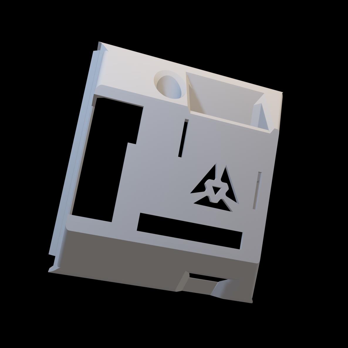
Back enclosure showing cooler clearance and cable routing
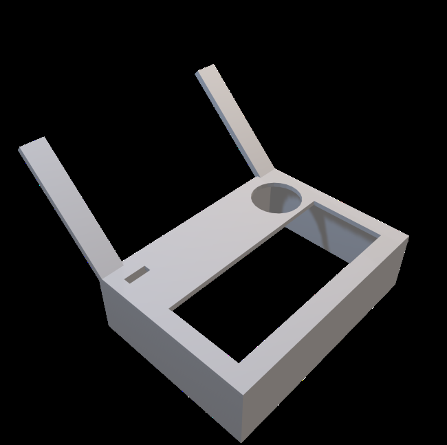
Screen-side enclosure showing display mount and port placement
Demo
Results
The system deployed and performed as intended. Real-time thermal imaging worked reliably through the touchscreen interface, sensor swaps worked without rebooting, and the Wi-Fi + Bluetooth connections held up throughout testing. The AMG8833's 8×8 resolution is low by camera standards, but more than sufficient for detecting heat signatures on machinery surfaces.
The thermal map visualization clearly resolved heat distribution across a motor surface; hotspots showed up immediately and tracking them across swap cycles required no user configuration.
Live thermal output from the AMG8833 8×8 grid, upscaled to 300×300px with ironbow colormap
Future Work
Reprint enclosure in TPU for better durability and shock resistance in the field
Replace DuPont connectors with Deutsch connectors for watertight, secure connections
Add ultrasonic and vibration sensor modules to the swap library
Improve the UI with better graphs and customizable display options per sensor type
Enable wireless data logging to cloud storage for remote monitoring
Reduce cost by sourcing components in bulk or finding equivalent alternatives
Documentation
Full project report and presentation deck from ETC 423.